Horizontal Stress in a Plate in Plane Stress
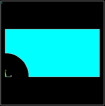
Plate is 40 inches x 20 x thickness = 0.1 with a 10 dia central Hole.
Use symmetry and model a quadrant of the plate.
Use Notepad or another text editor to create the text file shown below and save it somewhere convenient.
From the Windows menu start ANSYS (Not ANSYS Workbench)
Read the information in the text file into ANSYS using File > Read input from.../batch /FILNAM,scf /title Stress Concentration Geometry
! Example of creating geometry using keypoints, lines, cylinders. 10-6-98 KLL
/prep7
! Create geometry
k, 1,  0.,  0.      ! Keypoint 1 is at 0.0, 0.0
k, 2, 20.,  0.
k, 3, 20., 10.
k, 4,  0., 10.
L, 1, 2             ! Line from keypoints 1 to 2
L, 2, 3
L, 3, 4
L, 4, 1
AL, 1, 2, 3, 4 ! Area defined by lines 1,2,3,4
cyl4, 0.0, 0.0, 5. ! Circular area at 0.,0., rad = 5.
asba, 1, 2 ! Area Subtract Area, 2 from 1
The geometry shown below is created.
(As an alternative you can do this interactively following Tutorial 3.B)

Interactively enter the following information using the menu picks indicated. At any point select File > Save as to save the model in the ANSYS *.db format.
Preprocessor -> Element Type -> Add -> Solid -> Quad 8node183 -> OK
Select the Triangluar Shape option.
Options (Element shape K1) > Triangle
Select the option where you define the plate thickness.
Options (Element behavior K3) > Plane strs w/thk > OK > Close
Enter the plate thickness.
Preprocessor > Real Constants > Add/Edit/Delete > Add > OK
Enter 0.1 > OK > Close
Preprocessor -> Material Props -> Isotropic (Enter values for Ex and prxy)
Preprocessor > Material Props > Material Models (Double click) > Structural > Linear > Elastic > Isotropic (Enter values for Ex and prxy)
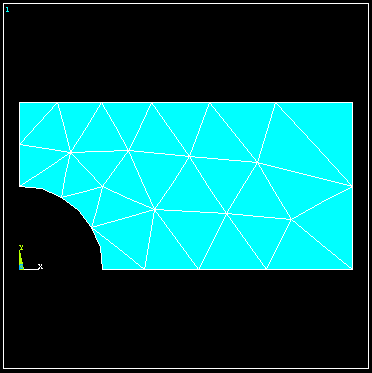
Preprocessor > Meshing > Mesh > Areas > Free (Select the area shown above)

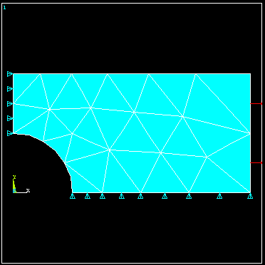
Main Menu > Preprocessor > Loads > Define Loads > Apply > Structural > Displacement > On Lines Pick the bottom edge of the quadrant > OK > UY = 0. > OK
(Repeat for the left edge and set ux = 0)
Preprocessor -> Loads -> Apply -> Pressures -> On lines (Select vertical edge on right & enter pressure = -100 to give tensile loading)

Solution -> Solve -> Current LS
Main Menu > General Postproc > Read Results > First Set
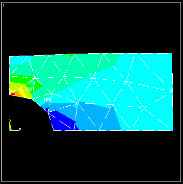
Main Menu > General Postproc > Plot Results > Contour Plot > Element Solu > Stress > X-Component of stress > OK

The discontinuous stress contours across element boundaries indicates a potentially significant error in the solution with this mesh. The mesh could be refined to obtian more accurate results. See Example 3.C.
To display the solution Strain Energy
Main Menu > General Postproc > Plot Results > Contour Plot > Element Solu > Energy > Strain Energy
To list the Strain Energy
Main Menu > General Postproc > Element Table > Define Table > Add > Energy > Strain enrg SENE
Main Menu > General Postproc > Element Table > Sum of Each Item
Back