Problem
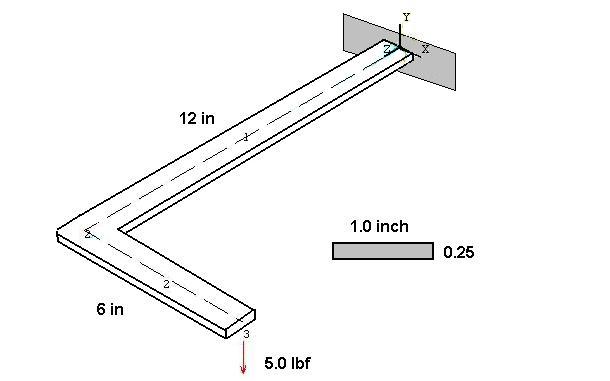
– Find the stresses and deflections of a steel ‘L' shaped beam with one end cantilevered and a point load at the other end.
Solution – The ANSYS 3D beam element ‘beam4’ is used in modeling this problem. When a beam element is incorporated in a 3 dimensional model, the full 3D flexibility of the beam must be considered. That is, it can have axial deformation, torsional deformation, and bending deformations in two principal bending planes. Thus, each beam element of the model must be positioned in space to reflect the proper orientation of the element cross section. This can be accomplished using an angular rotation ‘theta’of the element about its longitudinal axis or by employing three node points to define a principal plane of bending for the element. This example uses the latter approach that is illustrated below.
The element above connects nodes a and b. The third node, c, is used to define the local x-z plane which is one of the principal planes of bending for the cross section. Node c can be another node in the model or a dummy node (with all DOF set to zero) that is just used for orientation purposes. The beam cross sectional properties are defined by a ‘Real Constants’ set and entered accordingly. The values for Izz and Iyy must correspond to the orientation specified by the three nodes. Check your work carefully. It’s easy to get Izz and Iyy reversed.
The Global axis (X,Y,Z) and local axis (x,y,z) definitions for the two elements of the current problem are illustrated below.
Note: The geometric property constant Ixx is the torsional stiffness constant for cross section. For circular sections Ixx is equal to the polar moment of inertia (Iyy + Izz). For non-circular sections the torsional stiffness constant is not equal to the polar moment of inertia (see torsion of non-circular section in a solid mechanics reference). If no value is entered for Ixx, ANSYS will compute the torsional stiffness constant as Iyy + Izz which is correct for circular sections but not correct for non-circular sections.
/FILNAM,el_beam
/title 3D Beam Sample Problem – An 'L’ - Beam
/prep7

! Displacements & stresses in an 'L' shaped beam, 10-8-98 KLL
n, 1,  0.0,  0.0,  0.0   ! Node 1 is located at (X=0.0, Y=0.0, Z=0.0)
n, 2,  0.0,  0.0, 12.0
n, 3,  6.0,  0.0, 12.0

et, 1, beam4                 ! Element type; no.1 is 3D beam

!Material Properties
mp, ex, 1, 1.e7              ! Elastic modulus, psi
mp, prxy, 1, 0.3             ! Poisson’s ratio

! Real properties for beam with 0.25 x 1.0 cross section
! (6 values on first line. 'rmore' for additional values.)

! "r", Set number, Area, Izz, Iyy, thick-z,thick-y,theta,
r, 1, 0.25, 0.001302, 0.0208, 1.0, 0.25, 0

! "rmore", intl strain, Ixx,shear-z,shear-y,spin,addmass
rmore, 0, .004388, , , ,

! element connection and orientation
en, 1, 1, 2, 3       ! Element #1 connects nodes 1 & 2, and
                     ! uses node 3 to define the element local x-z plane.

en, 2, 2, 3, 1       ! Element #1 connects nodes 2 & 3, and
                     ! uses node 1 to define the element local x-z plane.

! Displacement boundary conditions
d, 1, ux, 0.             ! Displacement at node 1 in x-dir is zero
d, 1, uy, 0.
d, 1, uz, 0.
d, 1, rotx, 0.           ! Rotation at node 1 about x-axis is zero
d, 1, roty, 0.
d, 1, rotz, 0.
! (Could have used d, 1, all, 0.0 to define root restraint.)

! Applied force
f, 3, fy, -5.0           ! Force at node 3 in y-direction
finish


/solu                    ! Select static load solution
antype, static
solve
save
finish


/post1
etable, smax, s, max     * Create a table of element stress values
The deformed beam is shown in the figure below. Nodes were only used at the ends of the ‘L’ segments so the deformed shape shows a straight-line connection between nodes. The calculated deformations are correct however. You can check the results using superposition or energy methods.
PlotCtls -> Numbering -> Node numbers ON, Element numbers ON
PlotCtls -> Symbols -> Applied B.C.'s
General Postprocessor -> Plot Results -> Deformed Shape -> Def. + Undef.
(c) Copyright 1998-2002 Kent L. Lawrence. All rights reserved. Last update 1-6-02.