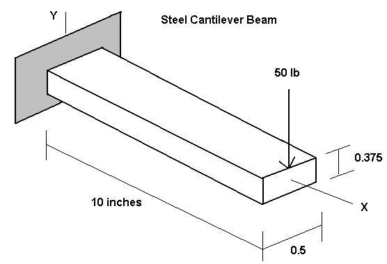
Problem: Determine the end deflection and root bending stress of a steel cantilever beam modeled as a 2D problem.
Solution: The ANSYS 2D beam element 'beam3' is used for modeling. The ten-inch long beam is represented by ten beam3 elements connecting 11 nodes along the global X-axis. Displacement boundary conditions at the left end restrain axial, vertical and ThetaZ movement.
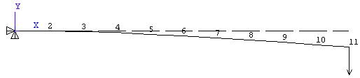
(Note: The displacement and stress solution for this problem is solved just as accurately with ONE 10 inch long element connecting two nodes. The deformed shape plot however would show a straight line connecting the two nodes. If examining the deformed shape is important or if the spatial mass distribution needs to be accurately represented, use several nodes along the length as described above, otherwise two nodes will do the job.)
The problem is formulated in a consistent set of units (pounds force and inches in this case) so that the computed results will be in terms of those units.
/FILNAM,beam1
/title 2D Beam Sample Problem 1 - 10 elements
! Ten element 2D beam Sample Problem
/prep7
!List of Nodes
n, 1, 0.0, 0.0 ! Node 1 is located at (0.0, 0.0)inches
n, 2, 1.0, 0.0
n, 3, 2.0, 0.0
n, 4, 3.0, 0.0
n, 5, 4.0, 0.0
n, 6, 5.0, 0.0
n, 7, 6.0, 0.0
n, 8, 7.0, 0.0
n, 9, 8.0, 0.0
n, 10, 9.0, 0.0
n, 11, 10.0, 0.0
et, 1, beam3 ! Element type; no.1 is beam3
!Material Properties
mp, ex, 1, 3.e7 ! Elastic modulus for material number 1 in psi
mp, prxy, 1, 0.3 ! Poisson’s ratio
mp, dens, 1, 0.283/386 !Mass density
! Real constant set 1 for a 0.5 x 0.375 rectangular xsctn beam.
! Area, Izz (flexural Inertia), height 'h' as in sigma = Mc/I, c = h/2
! A = 0.1875 sq.in., Izz = 0.0022 in^4, h = 0.375 inch
r, 1, 0.1875, 0.0022, 0.375
!List of elements and nodes they connect
en, 1, 1, 2 ! Element Number 1 connects nodes 1 & 2
en, 2, 2, 3
en, 3, 3, 4
en, 4, 4, 5
en, 5, 5, 6
en, 6, 6, 7
en, 7, 7, 8
en, 8, 8, 9
en, 9, 9, 10
en, 10, 10, 11
!Displacement Boundary Conditions
d, 1, ux, 0.0 ! Displacement at node 1 in x-dir is zero
d, 1, uy, 0.0 ! Displacement at node 1 in y-dir is zero
d, 1, rotz, 0.0 ! Rotation about z axis at node 1 is zero
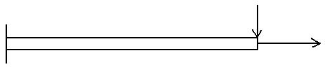
!Applied Force
f, 11, fy, -50. ! Force at node 11 in negative y-direction is 50 lbf.
/pnum, elem, 1 ! Plot element numbers
eplot ! Plot the elements
finish
/solu ! Select static load solution
antype, static
solve
save
finish
/post1
etable, stress-x, s, max ! Create a table of element stress values
! P/A + Mc/Izz
To examine the computed deflections
General Postproc > List Results > Nodal Solution . . .> DOF Solution All DOF
PRINT DOF  NODAL SOLUTION PER NODE

  ***** POST1 NODAL DEGREE OF FREEDOM LISTING *****

  LOAD STEP=     1  SUBSTEP=     1
   TIME=    1.0000      LOAD CASE=   0

  THE FOLLOWING DEGREE OF FREEDOM RESULTS ARE IN GLOBAL COORDINATES

    NODE      UX          UY          ROTZ
       1   0.0000      0.0000      0.0000
       2   0.0000    -0.36616E-02-0.71970E-02
       3   0.0000    -0.14141E-01-0.13636E-01
       4   0.0000    -0.30682E-01-0.19318E-01
       5   0.0000    -0.52525E-01-0.24242E-01
       6   0.0000    -0.78914E-01-0.28409E-01
       7   0.0000    -0.10909    -0.31818E-01
       8   0.0000    -0.14230    -0.34470E-01
       9   0.0000    -0.17778    -0.36364E-01
      10   0.0000    -0.21477    -0.37500E-01
      11   0.0000    -0.25253    -0.37879E-01

 MAXIMUM ABSOLUTE VALUES
 NODE          0          11          11
 VALUE    0.0000    -0.25253    -0.37879E-01
The maximum slope and deflection occur at the free end as expected. The values –0.037879 Rad and –0.25253 inch agree with results you can calculate from solid mechanics beam theory. (Try it and see.)
To examine the computed bending stress
General Postproc > List Results > Element Table Data > Stress-X

 PRINT ELEMENT TABLE ITEMS PER ELEMENT

  ***** POST1 ELEMENT TABLE LISTING *****

    STAT    CURRENT
    ELEM    STRESS-X
       1   42614.
       2   38352.
       3   34091.
       4   29830.
       5   25568.
       6   21307.
       7   17045.
       8   12784.
       9   8522.7
      10   4261.4

 MINIMUM VALUES
 ELEM         10
 VALUE    4261.4

 MAXIMUM VALUES
 ELEM          1
 VALUE    42614.
The maximum bending stress of 42,614 psi occurs in beam element 1 at the support and the value agrees with what you would compute using elementary beam theory.
Axial stiffness is included in the beam3 element formulation, so we could add an axial force to the above problem and compute the axial stress and deformation as well. Note however that in the linear approach discussed here, the axial and bending deformations are uncoupled. That is, the presence of an axial stress does not influence the bending stiffness. If the bending deformation is small, this approach is usually completely satisfactory.
On the other hand, for large deformations the nonlinear coupling of axial stress and bending stiffness must be considered, and nonlinear solution options employed. What’s large and what’s small a given problem? Some previous experience and/or numerical experimentation can help answer that question.
(c) Copyright 1998-2002 Kent L. Lawrence. All rights reserved. Last updated 1-6-02.