4-1 Computational Aspects
The steps involved in the formulation and solution of a typical finite element problem are summarized below.
1. Define the geometry; identify nodes & elements.
2. Establish convenient reference coordinate system(s).
3. Compute the stiffness matrix for each element.
4. Assemble the element stiffness matrices to form the global stiffness matrix K.
5. Consider the boundary conditions imposed on nodes.
6. Find the global load vector R.
7. Solve the global equation set R = K D for the global displacement vector D.
8. Find the stresses, strains, etc. in elements and display the results.
The most time consuming step in this process is the one in which the global equation set is solved to determine the displacement vector, that is, the solution of
For K to be nonsingular, all possible rigid body motions must be restrained by boundary conditions. Symbolically we write D = K-1 R, however, inversion of K is an expensive process, and for practical problems, other methods should be used such as a matrix factorization or iterative solution method.
Linear Static Response
To define a finite element problem, you must supply the following information to an FEM computer code.
(1) List of nodes
Node no x y z
1 - - -
2 - - -
(2) List of elements element no, element type, which nodes are connected, reference to geometric property reference to material properties
(3) List of materials and their properties.
(4) Boundary conditions: ![]() , etc
, etc
(5) Loadings Point forces, point moments pressures of surfaces,loads proportional to mass body loads
Example

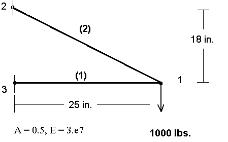
The truss in the accompanying figure serves as an illustration of the input data required to define a simple FEM model.
The text file below describes this problem for input to the FEM program ANSYS and includes the major input items as described above.
/batch
/FILNAM,truss
/title Simple Truss
/prep7
n, 1, 25.0, 0.0, 0.0 * Node 1 is located at (25.0, 0.0, 0.0)
n, 2, 0.0, 18.0, 0.0
n, 3, 0.0, 0.0, 0.0
et, 1, link1 * Element type; no.1 is link1
mp, ex, 1, 3.e7 * Material Properties, E for material no. 1
mp, prxy, 1, 0.3 * & poisson's ratio for material no.1
r, 1, 0.5 * 'Real Constant' number 1 is 0.5
* (Cross sectional area)
en, 1, 3, 1 * Element Number 1 connects nodes 1 & 2
en, 2, 2, 1
d, 3, ux, 0. * Displacement at node 3 in x-dir is zero
d, 3, uy, 0. * Displacement at node 3 in y-dir is zero
d, 2, ux, 0.
d, 2, uy, 0.
f, 1, fy, -1000. * Force at node 1 in y-direction is -1000.
Methods for obtaining solution to the FEM equations are discussed in the next sections.