3-1 Truss Element Stiffness Matrix Transformation

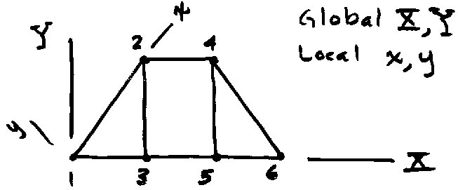
It is easy to assemble truss elements that all are aligned with the global axis system as was done in earlier examples. In most practical two-dimensional structural models, elements that are not aligned with global coordinates must be assembled to construct the appropriate model. The describing variables for such elements must be transformed to the global reference before assembly can be performed.
Transformation of Displacements
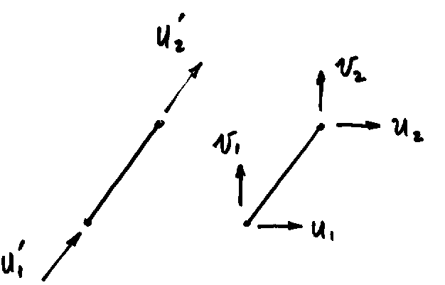
To accomplish this it is convenient to establish a local axis system aligned the element axis as shown next. Let x be directed from element node 1 to element node 2. At each node the local axis displacement variables are u’ and v’. The corresponding variables in the global reference are u and v.
From the figure we find the following transformations.
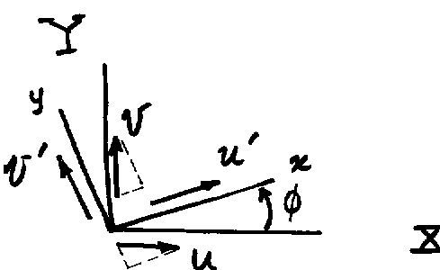
u’ = u cos f + v sin f
v’ = -u sin f + v cos f
![]()
This equation gives the displacements in local coordinates in terms of those in the global coordinates system.
{d’} = [t] {d}
Where for a single node
![]()
(Note that we use {d} to represent both the variables at a single node and the variables at all nodes of the element. The distinction should be clear from the context.)
The truss element stiffness expressed in local coordinates has the form
{r’} = [k’] {d’}
Or

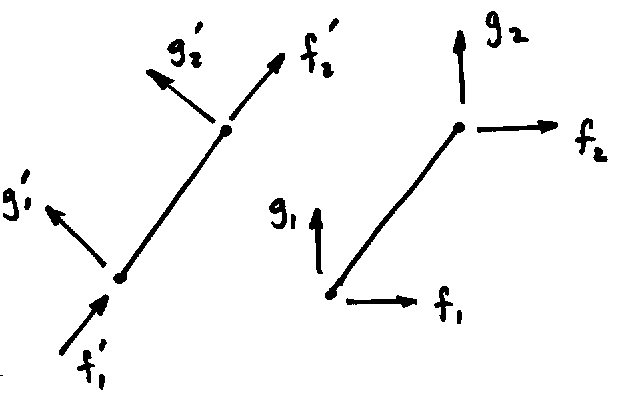
Since the truss is a two-force member, there are no forces in the y direction. We can expand the truss stiffness matrix to include the y components by adding the requisite zeros as shown in the equation below.

The transformation then takes the following form.
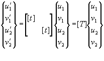
or
{d’} = [T] {d}
where, including both nodes of the truss element, {d} takes the following form.

The expression {d’} = [T] {d} can be substituted into the element stiffness equation to give.
{r’} = [k’] {d’} =[k’][T]{d}
Transformation of Forces
In the above, the element displacements were transformed from the element coordinate system to the global system. To determine the expression for the element forces in the global system, we compute the work done by the element forces in both local and global coordinate systems. Work is a scalar and therefor independent of coordinate system, so the two expressions must be equal.
In global coordinates, the work of element nodal forces acting through element nodal displacements is given by.
Work = (1/2) {d}T {r}
And in the element system
Work = (1/2) {d’}T {r’}
Thus
{d}T {r} = {d’}T {r’}
From the displacement transformation development above, we have
{d’} = [T] {d}
Taking the transpose of this expression gives.
{d’}T = {d}T[T]T
Now substitute this into the expression for work equivalence
{d}T {r} = {d’}T {r’} = {d}T[T]T {r’}
From which we observe that
{r} = [T]T {r’}
This expression gives the relationship between the element load vector in global and element reference systems.
Transformation of the Element Stiffness Matrix
The truss element stiffness matrix is most conveniently derived using coordinates aligned with element geometry, but the results found above can be used to express the element stiffness matrix in global coordinates.
In element coordinates
{r’} = [k’] {d’}
Substitute {d’} = [T] {d} to give
{r’} = [k’] {d’} = [k’] [T] {d}
Now multiply by [T]T to give
[T]T {r’} = [T]T [k’] [T] {d}
But, since {r} = [T]T {r’}, we have
{r} = [T]T [k’] [T] {d} = [k] {d}
And we arrive at the following expression that transforms the element stiffness matrix from element coordinate reference to global coordinate reference.
[k] = [T]T [k’] [T]
Once an element stiffness matrix of a finite element model has been transformed from local to global coordinates, it can be combined with previously transformed element stiffness matrices to form the global stiffness matrix for the problem.