2-5 Assembly of Two Beam Elements

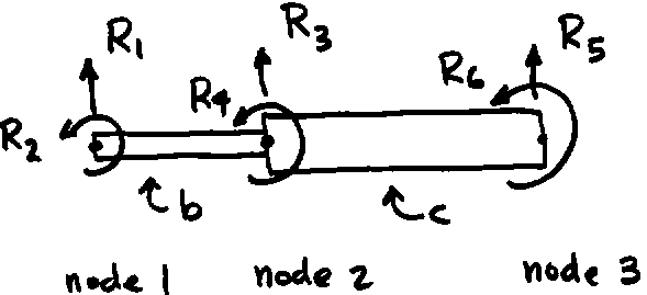
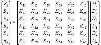
Consider two beam elements, 'b' and 'c' of different cross sections, lengths, and materials that are joined together to form the simple structure shown in the figure. We want to determine the matrix relationship between the external loadings applied to the structure, R1, R2, . . . ,R6 , and the resulting node point displacements of the structure, D1, D2, . . . ,D6. That is, we want to determine the 6x6 stiffness matrix K in the following equation.

![]()
The global stiffness matrix for the structure can be obtained through assembly of the two beam element stiffness matrices for components 'b' and 'c'. The stiffness matrix for element 'b' is:


Where the superscript b is used to denote properties for beam element ‘b’. A similar expression is written for element 'c':

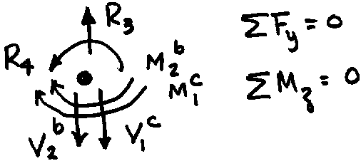
To establish the equilibrium condition among the loadings, draw a free body of each node showing the externally applied loadings, R and the loadings applied by the elements on each node. The loads at node 3 are shown in the figure.
Equilibrium of loads at node 3 requires:
![]()
![]()
![]()
![]()
Write now the expressions for the element node point shear forces and bending moments by using the element stiffness matrix terms multiplying the element node displacement and slope variables (v1)b, (q 1)b, etc, similar to the process used for the truss element assembly.
Next establish compatibility between the displacement notations, that is,
![]() ,
, ![]() ,
, ![]() , etc
, etc
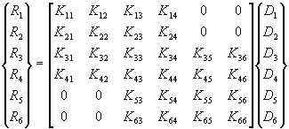
Substituting these into the equilibrium equations and collecting terms gives the assembled stiffness matrix with the following form:

The zero terms show no direct coupling of global quantities such as R1 and D5. Boundary conditions must be applied to the global stiffness matrix and, solution of the resulting system of equations gives the displacements and bending slopes for the assembled structure.