2-4 Beam Element
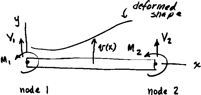
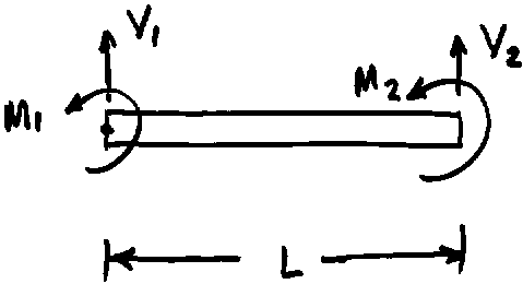
The uniform, homogeneous beam element shown has a node at each end where displacement and rotation deformation variables v and q are defined. The beam flexural inertia is I, the material modulus of elasticity is E, and its length is L.

Shear force and bending moment loadings at each node are denoted by V and M. We will use elementary solid mechanics principles to develop the relationship between loadings and deflections.
The figure below shows a free body diagram of a segment of the beam cut at a distance x
from the left end.
The moment at x is given by M(x) = V1 x - M1
The deformation and loadings are related by the moment-curvature expression below where v is the transverse displacement of the neutral axis of the beam.
![]()
Integrate this equation to get expressions for the beam slope and deflection
![]()
![]()
Here c1 and c2 are constants of integration. These two equations describe the behavior of a uniform beam subject to loadings at either end of the element.
Since there are two discrete variables at each node point, the beam element stiffness matrix is 4 by 4.

As with the truss element, each column of the beam element stiffness matrix can be
thought of as the node point loadings necessary to cause a certain characteristic
displacement pattern. The first column corresponds to a deformation state of
v1 = 1, q 1 = 0, v2 = 0, q 2 = 0
The equations for beam slope and displacement have four unknown quantities, V1, M1, c1 and c2, and there are four deformation conditions for the characteristic deflection pattern given above.
Applying these four conditions gives:
At x = 0, v1 = 1; ![]() Thus, c2
= 1.
Thus, c2
= 1.
At x = 0, q 1
= 0; ![]()
At x = L, v2 = 0; 
At x = L, q 2
= 0; ![]()
The nodal shear force and bending moment at the left end are found by solving the last two equations to give
![]()
![]()
Equilibrium of the beam element requires that

V1 + V2 = 0
M1 + M2 – V1L = 0
Solving for the shear force and bending moment at the right end gives V2 and M2
![]() and
and ![]()
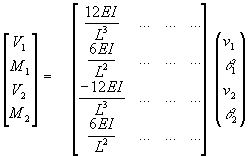
The results for V1, M1, V2 and M2 constitute the first column of the beam element stiffness matrix as shown below.

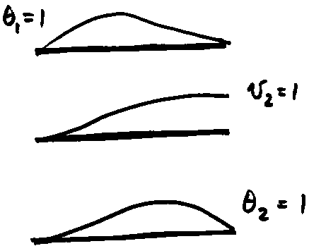
The remaining columns in the beam stiffness matrix can be found by applying displacement patterns of

v1 = 0, q 1 = 1, v2 = 0, q 2 = 0
v1 = 0, q 1 = 0, v2 = 1, q 2 = 0
v1 = 0, q 1 = 0, v2 = 0, q 2 = 1
Repeating the process described above, the result is

![]()
This beam element stiffness matrix considers bending actions only.