Assigned 10-10-06; Due 10-17-06
(a) Use a 2D beam element FEM model to find the end displacement and maximum bending stress in a cantilever beam with a concentrated load on the free end. Compare your result with solid mechanics theory. Use both 1 element and 10 element models. Pick your own dimensions, load, and material. See ANSYS Tutorial Chapt 5 and ANSYS Example 7.A
(d) Work text problem 6.3-6 Part (a) and problem 6.3-7 Parts (a.) and (c).
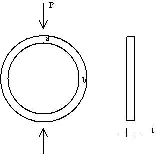
(c) A thin aluminum ring of inner radius r1 = 105 mm, outer radius r2 = 110 mm and thickness (in the 'z' direction) t = 5.0 mm is subjected to a load P = 10 N applied along its diameter. Relative to the center of the ring, find the vertical displacement of point 'a' and the horizontal displacement of point 'b'.
Use symmetry and model only one quadrant of the ring. 2-D Beam elements can be used to model the bending of the thin ring. Employ 2, then 4, and then 8 straight beam elements to model one quadrant and record the displacement solutions computed. To compare your results to the theoretical solution, plot the per cent error in computed displacement vs. number of elements used. The theoretical solution is given below.
R = (r1 + r2)/2, I = xsctn area moment of inertia, E = elastic modulus, pi = 3.141592...
Vert disp of 'a' = PR^3 (pi/4 - 2/pi)/(2EI)
Horiz disp of 'b' = PR^3 (1/pi - 1/4)/(EI)

Back