Cosmetic Threads
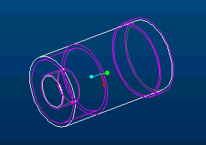
The presence of a threaded surface can be shown without actually creating a solid model of the threads themselves. Circles indicate the major and minor thread diameters just as when creating drawings manually. The part below has external and internal threaded surface on the left end and an up-standing external thread on the right.

An example of creating a cosmetic an external thread feature on a 1.25 inch diameter shaft in Pro/E is shown next. The thread is be a UNC thread 0.75 inches long with a pitch of 7 threads per inch.
First create a cylindrical protrusion 1.25 inches in diameter and 3.0 inches long.
Feature > Create > Cosmetic > Thread
Select the threaded surface > select the external surface of the cylinder
Select the thread start surface > select one end plane of the cylinder
DIRECTION> Flip or OKAY
SPEC TO > Blind > Done
Enter depth (ie, length of threaded surface), 0.75
Enter DIAMETER > 1.0747
(This is the minor diameter for external threads and the major diameter for internal or upstanding threads. Pro/E suggests a value to use for the diameter. Ignore the warning ‘Thread geometry will be created outside the part.’)
FEAT PARAM > Mod Params
(A table is shown containing the following information about the threads. Edit values to supply the appropriate information.)
MAJOR_DIAMETER 1.25
THREADS_PER_INCH 7
FORM UNC
CLASS 2
!Thread Placement (A=external, B=internal)
PLACEMENT A
!Thread is metric (True or False)
METRIC FALSE
Save data and quit. (This information is attached to the cosmetic thread feature and is available for review by selecting Feature Info.)
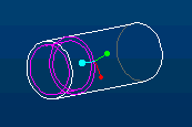
Preview gives

and accept feature definition with OK.
© Copyright 1999 Kent L. Lawrence. All rights reserved.