MAE 4344 - Computer Aided Engineering
Homework assignments are individual assignments due at the begining of class on the Due date.
Use a COVER SHEET (see syllabus).
Work Sheets are partner assignments due as indicated. No cover sheet reqd.
Be sure to read the Syllabus Homework Format instructions and the Mavspace file 'Home Work Format' before preparing your solutions.
Note that Problems are not assigned until the indicated date is for the current semester.
'ENGR PROBS' Require complete engineering documentation.
Express your computed results using 3 to 4 significant digits accuracy unless otherwise indicated and convert computed results so as to be able to present results in both systems of generally accepted units for engineering work. That is, work the problem using the units in which it's defined, show the computed results in those units, and convert the results so that you can present answers in both MKS (mm KS) and IPS (FPS) systems. See ANSYS Workbench Tutorial 4A.
'TUTORIALS' Only require the indicated results as 'deliverables'.
You can find many unkown material properties at www.matweb.com
HW #1 Assigned 1-16-19, Due 1-22-19 Remember to put a cover sheet on your assignment.
a. Submit a dimensioned, hand-drawn, four-view (front, side, top, isometric) sketch of one half of a door hinge to which you have access. (Room door, car door, cabinet door, etc.) Use a ruler to determine the approximate dimensions but don't use a straight edge to make the drawing, just make a sketch. Block print MAE 4344, your name and the date in a Title Block on the lower right-hand corner of the drawing sheet. Take a picture of the object with a digital camera. The drawing sheet and a print of the photograph is all that is required to document the solution to this assignment.
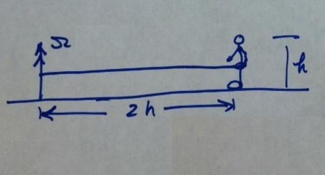
b. A person is chopping wood with an axe. The hands gripping the axe are spread apart about the width of two hands. Draw a free body diagram of the axe just as it hits the wood at the lowest point on the swing.
HW #2 Assigned 1-27-19, Due 1-31-19
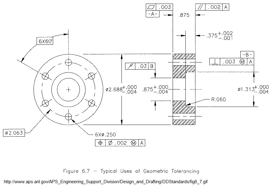
a. TUTORIAL Use Creo, SolidWorks or CATIA to create the solid model shown in the figure below. Estimate any dimensions not given. Submit an undimensioned plot showing the model in wireframe with dashed or grayed hidden lines. Put your name and date on the print and submit a print of the image. Assign Aluminum material to the part and report its mass properties
See www.schroff.com > SDC Publications books for ... > CAD > Pro/ENGINEER > Creo Parametric 5.0 Tutorial > Roger Toogood Free Chapter > Lesson 2
https://www.sdcpublications.com/Textbooks/SOLIDWORKS-2016-Engineering-Graphics/ISBN/978-1-63057-000-2/b. TUTORIAL Use Creo, SolidWorks or CATIA to create a solid model for the part on pages 3-5 the Shih book referenced below. Submit a wireframe print as before.
See SDC book SolidWorks 2016 and Engineering Graphics, An Integrated Approach, Randy H. Shih. Download free Chapt 3.
https://www.sdcpublications.com/Textbooks/SOLIDWORKS-2016-Engineering-Graphics/ISBN/978-1-63057-000-2/
HW #3 Assigned 2-1-19, Due 2-7-19
To receive credit be sure to document Engineering Problems appropriately.
ENGR PROB. A 150 in (overall length) cylinder with spherical closed ends has ID = 20 in and OD = 40 in and is subjected to an internal pressure of 16,000 psi. Make a good, hand-drawn sketch to scale of the cylinder and another of a segment of the wall at the mid-length of the cylinder and clearly identify the reference XYZ axis system you will be using.
Use thick-walled cylinder theory to compute the hoop, radial, and axial stresses at a point in the cylinder on the inner surface at mid-length. Make a sketch of a small cubic element showing your stress results at the inner surface. Give the coordinate axis directions for each component, Sx, Sy, Sz. Determine the principal stresses S1, S2, S3 and the von Mises stress Sv at this point. Present your computed stress results in both PSI and MPa; use 4 significant digits but no more.
Calculate the hoop stress by hand, then see this link for a JavaScript calculator.
http://www.engineeringtoolbox.com/stress-thick-walled-tube-d_949.html
a. If the cylinder is made of AISI 1040 as rolled steel, explain why yielding will or will not occur. Compute the Factor of Safety with respect to yielding. Compute the Margin of Safety.
Look on www.MATWEB.com to find the properties of AISI 1040 Steel and Gray Cast Iron.
b. If the cylinder is made of Gray Cast Iron, ASTM A 48 Class 40 (see matweb), explain why fracture will or will not occur. Compute the Factor of Safety with respect to fracture. Compute the Margin of Safety.
c. Create a solid model of the cylinder and submit a wire-frame print of the model.
d. Use your solid modeler to compute and report the mass properties of the steel cylinder in MKS & IPS units. Find the angular acceleration if it is free to rotate about its longitudinal axis of revolution and a torque of 80 in-lbf is applied.
Review the syllabus discussion of homework procedures and the Blackboard file Home Work Format
e. TUTORIAL Work through ANSYS Examples 2.C Truss2 on our site mae.uta.edu/~lawrence/mae4344/mae4344.htm > ANSYS Submit the undeformed/deformed shape image showing boundary conditions & loads, element and node numbering. Also find the location and magnitude of maximum displacement.
HW #4 Assigned 2-9-19, Due 2-14-19
a. ENGINEERING PROB. You are standing on an amusement park ride rotating at 12 RPM. A cable restrains you radially and the frictionless floor vertically. Draw a free body of you on the ride. Find the force in the cable Fc. Solve this problem in IPS units then in MKS units.
(The acceleration of the amusement park rider is (omega^2)*R where R is the distance from the center of rotation to the individual. The acceleration is directed from the individual toward the center of rotation.)
b. Look up the distance from Arlington, TX to Los Angles, CA. express your answer in Miles, Kilometers, Angstroms and Light Years.
c. TUTORIAL Create solid models for the Tutorial Lessons 4 and 6 for extra practice. Submit an undimensioned, wireframe plot. Select suitable values for any missing dimensions. No problem statement is required. Put your name and date on the prints and submit hard copy of the wireframe plots.
HW #5 Assigned 2-18-19, Due 9-21-19
TUTORIAL Work through ANSYS Examples 3.A Plane Stress. Submit the last image.
a. TUTORIAL Work through Blackboard > WBtutorialCh4 > WBtutorial-Ch4 STEP.pdf > Slides 1-33. Submit the image of slide 33.
b. Same as a. but slides 37-52. Submit slide 52 image.
c. ENGR PROB Blackboard > WBCh4Problems.pdf > Problem 4.1
HW #6 Assigned 2-28-19, Due 3-7-19
a. Consider the long, thin structural steel beam 0.25 x 1.5 x 12.0 inches, fixed at one end, free at the other. Apply a pressure of 150 psi on the upper 0.25 x 12.0 surface. Compute the vertical deflection at the free end and the maximum bending stress at the top edge at mid length of the beam. Look up the theoretical solution in your solid mechanics book and compare your FEM results with the results you can compute from beam theory. Submit an image of the 'environment' loads and BC as well as the stress solution including your mesh.
Also compute the Vertical Shear Stress at the neutral axis at mid length. Compare Workbench results with solid mechanics beam theory results. (VQ/It).
Compute and observe the 'Element Order - linear' and 'Element order - Quadratic' results.
b. A 20 inch diameter disk has an 8 in centreal square hole with 1.0 inch radius corner fillets. The cylinder thickness is 0.75 inch. Find the maximum values for von Mises stress, principal stress, shear stress, and displacement if the front and back surfaces have frictionless supports (condition of plane strain) and the interior has a pressure of 7500 psi.
c.Submit a proposal for your term project, just a sentence or two describing the project and who the team is. Include a hand drawn sketch of the object.
If you need extra solid modeling practice work on these parts and assembly Lesson 10.
HW#7 Assigned 3-26-19, Due 4-2-19
a. Refer to Blackboard > Course Materials > Session4 > Slides 33-40. Let kb = 300 lbf/in, kc = 500 lbf/in, R1 = F1 = 800 lbf, R2 = F2 = 0. Write the global stiffness matrix [K]. Use MATLAB or equivalent to find D1, D2 and R3.
b. An indefinitely long copper pipe of OD = 3.0 inch and ID = 1.75 has an internal temperature of 300 Deg F. Exterior to the pipe the environment is 80 deg F. The exterior convection coefficient is 0.3e-4 BTU/(sec-sq in-deg F). Find and plot the temperature distribution through the wall thickness of the pipe. (Ref WBTutorial 7A).
c. Work through 7.b above but use a 10 degree wedge model instead of the whole cross section.
d. Use ANSYS WB to compute the first four natural frequencies of a steel cantilever beam of dimensions 0.5 x 1.75 x 30 inches vibrating in the 0.5 cross section dimension direction (flat-wise). List the frequencies and sketch the corresponding modes of vibration. Compare your results with theoretical results using reference below.
Note that the beam can bend about both principal axes of its cross section. It can twist and stretch as well. Be sure to examine the each mode of vibration.
www.roymech.co.uk/Useful_Tables/Vibrations/Natural_Vibrations.html
HW#8 Assigned 4-3-19, Due 4-9-19
a. Use ANSYS Workbench to compute the linear elastic bucking load of a steel cantilever beam 30 inches long with a cross section 0.5 x 1.5 inches. (See WBCh9) Compare your results to solid mechanics theoretical reults.
b. Repeat the large deflection calculations for the cantilever beam described in Blackboard WB Chapter 10 slides 8 through 10 first with a steel beam. Then change the material to aluminum and repeat.
HW#9 Assigned 4-17-19 Due 4-23-19
Submit a progress report for your term project, just a sentence or two describing the project and how far along you are in your work. Include any images that show your work progress.
One report for each project not for each team member.
Be prepared to show me your progress during class. I'll walk around and look over your shoulder to see your work.
HW#10 Assigned 4-26-19, Due 5-2-19
a. Complete the 'Lifelong Learning Exercise' emailed to you. Respond to the questions and submit a hard copy of your answers.
Final Exam Questions The final exam will be a series of short questions based on the fundamentals discused during the semester. Please suggest and submit two questions to mae4344@mae.uta.edu for all of us to see.
Some samples from previous semesters:
1. What happens to the Applied Force F if only a quadrant of a symmetric part is to be analyzed? You should apply: a) F b) F/2 c) F/3 d) F/4
2. What happens in the above case if the applied loading is a pressure?
3. ANSYS Workbench provides tools for the user to analyze the behavior of these systems (circle ans).
Thermal and Mechanical
Electric and Magnetic
Fluid, Thermal and Magnetic
All of the above
4. In parametric solid modelling, Dimensions are variables whose values can be changed as the design process requires.
True False
5. One can use Unaveraged plots of ANSYS calculated stresses to evaluate the accuracy of the solution.
True False
6. The elastic modulus of Steel is smaller than that of Aluminum.
True False
7. Make a sketch of the 3D solid elements we used in this course. Including the nodes.
HW# Assigned , Due
a. TUTORIAL Create the part model for the Rapid Prototype part shown.
Use 'Emboss' or equivalent to put your initials on the part.
Name your part file so as to include your name. Save your part file in the part file format and in the STL format for rapid prototyping (check SolidWorks for this capability). email the STL file to lawrence@uta.edu
HW# Assigned , Due
a. Create solid models for the parts and assembly HW# 6 c. Lesson 10. Submit a wire frame print of the assembly. Also submit the assembly STP file to mae4344cae@gmail.com
b. TUTORIAL Work through Tutorial 5C. Submit Figs 5-36 and 5-38.
c. ENGR PROB Solve Text problem 5-10.
d. ENGR PROB Work Problem 6-5. Use a wedge model as suggested on page 5-11. Also determine if the life of the pressure vessel will be infinite for a pressure that is repeatedly applied. Use the ANSYS Stress and Fatigue tools and also verify the results by hand calculation.
HW# Assigned , Due
a. TUTORIAL Use Mavspace > 2. WorkbenchTutorials > WBtutorialCh7 > Slide 48 to work through Tutorial 7C and submit Figures 7-40, 7-43, the von Mises stress (the right-most image in 7-46). Use symmetry to avoid rigid body motion.
b. ENGR PROB Problem 7-9 except that the internal pressure is 6500 psi.
c. Submit Project Proposal
HW # Assigned , Due
a. TUTORIAL Work through Tutorial 9B and submit Figures 9-21 and 9-25.
b. ENGR PROB Text Problem 9-1.
HW # 13 Assigned , Due
a. ENGR PROB Text Problem 9-7.
b. TUTORIAL Work through Tutorial 9D and submit Figure 9-38. Also in your solid mechanics book look up the equation for the Euler buckling load for this kind of column (fixed-free) and check the result of this ANSYS calculation by hand.
HW #14 Assigned , Due
a. Go through WB Tutorial 10A. Submit Figs 10-10 and 10-11. Create the little patch on the end by bonding a 0.125 x 0.125 x 0.25 block to the end of a beam 4.875 inches long.
b. Work Problem 10-5 using solid elements.
HW 15# Assigned , Due
a. Find 'Lifelong Learning Exercise' in Mavspace Lifelong Learning folder. Respond to the questions and submit. This is a requirement of MAE 4344.
b. Turn in your Blue Book for review.
c. Read on Mavspace Solid Modeling Dynamics > 1. RotatingBar, 2. TwoBars and 7. SolidWorks (SolidWorks - Motion & SolidWorks_Motion_Tutorial_2013)as necessary.
Create a mechanism assembly that consists of the Base, the Bar (Bar1) with initial position horizontally to the right, and another Bar (Bar2) pinned to the end of the first bar and at 90 degrees with respect to the first bar. Save Bar2 as a separate part, put your initials on it and give it a color distinct from the other two parts in the assembly. Let both aluminum bars be 1.25 x 0.1 x 0.01 m.
Repeat the dynamic simulation described in the TwoBars tutorial with a constant speed 30 deg/sec input: run for one revolution of Bar 1; capture the motion animation file, measure and plot the bearing force at the joint between the Base and Bar1. Also measure and plot the relative angle between the two bars.
Put your name on the animation file and send it to me at lawrence@uta.edu.
HW Assigned , Due
Final Exam Questions The final exam will be a series of short questions based on the fundamentals as discused. Please suggest and submit two questions to mae4344@mae.uta.edu for all to see and discuss.
Some samples from a previous semester:
-----------------
1. What happens to the Applied Force F if only a quadrant of a symmetric part is to be analyzed?
You should apply: a) F b) F/2 c) F/3 d) F/4
-----------------
2. What happens if the applied loading is a pressure?
-----------------
1. Why is Static Structural Analysis with a unit loading performed before Linear Buckling Analysis?
It doesn't matter which analysis is performed first.
To determine if the material is safe or not.
To determine the internal distribution of compressive stress.
It is just a rule that needs to be followed.
-----------------
2. ANSYS Workbench provides tools for the user to analyze the behavior of these systems (circle ans).
Thermal and Mechanical
Electric and Magnetic
Fluid, Thermal and Magnetic
All of the above
1) In parametric solid modelling systems Dimensions are variables whose values can be changed as the design process requires.
True False
-----------------
2) One can use Unaveraged plots of ANSYS calculated stresses to measure the accuracy of the problem.
True False
-----------------
The elastic modulus of Steel is greater than that of Aluminum.
True False
Make a sketch of the solid elements we used including the nodes.