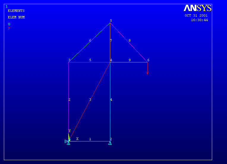
Truss2 – An example of the incorporation of multiple material and geometric properties in an ANSYS text file problem definition. Truss elements 1-5 are made of steel with 0.5 sq. inch cross section. Elements 6-9 are made of aluminum with 0.375 sq. inch cross section.

/FILNAM,truss2
/title Truss Sample Problem #2

/prep7

n, 1,  0.0,  0.0             ! Node 1 is located at (0.0, 0.0)
n, 2, 10.5,  0.0
n, 3,  0.0, 20.0
n, 4, 10.5, 20.0
n, 5, 10.5, 30.0
n, 6, 20.0, 20.0

et, 1, link1                 ! Element type; no.1 is link1

r, 1, 0.5                    ! 'Real Constant' number 1 is 0.5 (the link Cross sectional area)
r, 2, 0.375                  ! Second cross sectional area


! with ANSYS Release 13 link1 has been replaced by link180 and real 'constant' with 'sectype' and 'secdata'

! et, 1, link180             ! Element type; no.1 is link180
! sectype, 1, link           ! Type of cross section is link
! secdata, 0.5               ! Cross sectional area = 0.5 sq in


!First Material
mp, ex, 1, 3.e7              ! Material Property, Elastic modulus no. 1
mp, prxy, 1, 0.3

!Second Material
mp, ex, 2, 1.e7              ! Second material
mp, prxy, 2, 0.3

!The following elements are element type 1, made of material #1, with area real constant #1.

real, 1                      ! Set real & material properties for elements defined next.

mat, 1

en, 1, 1, 2                  ! Element Number 1 connects nodes 1 & 2
en, 2, 1, 3
en, 3, 1, 4
en, 4, 2, 4
en, 5, 3, 4


real, 2                      ! Switch to second set of real & material properties

mat, 2

!The following elements take new properties.

en, 6, 3, 5
en, 7, 4, 5
en, 8, 5, 6
en, 9, 4, 6

d, 1, ux, 0.                 ! Displacement at node 1 in x-dir is zero
d, 1, uy, 0.                 ! Displacement at node 1 in x-dir is -0.125
d, 2, uy, 0.

f, 6, fy, -1000.             ! Force at node 6 in y-direction

/pnum, elem, 1               ! Plot element numbers
eplot                        ! Plot the elements
/pbc, u, , 1

finish

/solu                        ! Select static load solution
antype, static
solve
save

finish

/post1
etable, stress, ls, 1        ! Create a table of element stress values