Axisymmetric Analysis - A problem in which the geometry, loadings, boundary conditions and materials are symmetric with respect to an axis is one that can be solved as an axisymmetric problem instead of as a three dimensional problem.
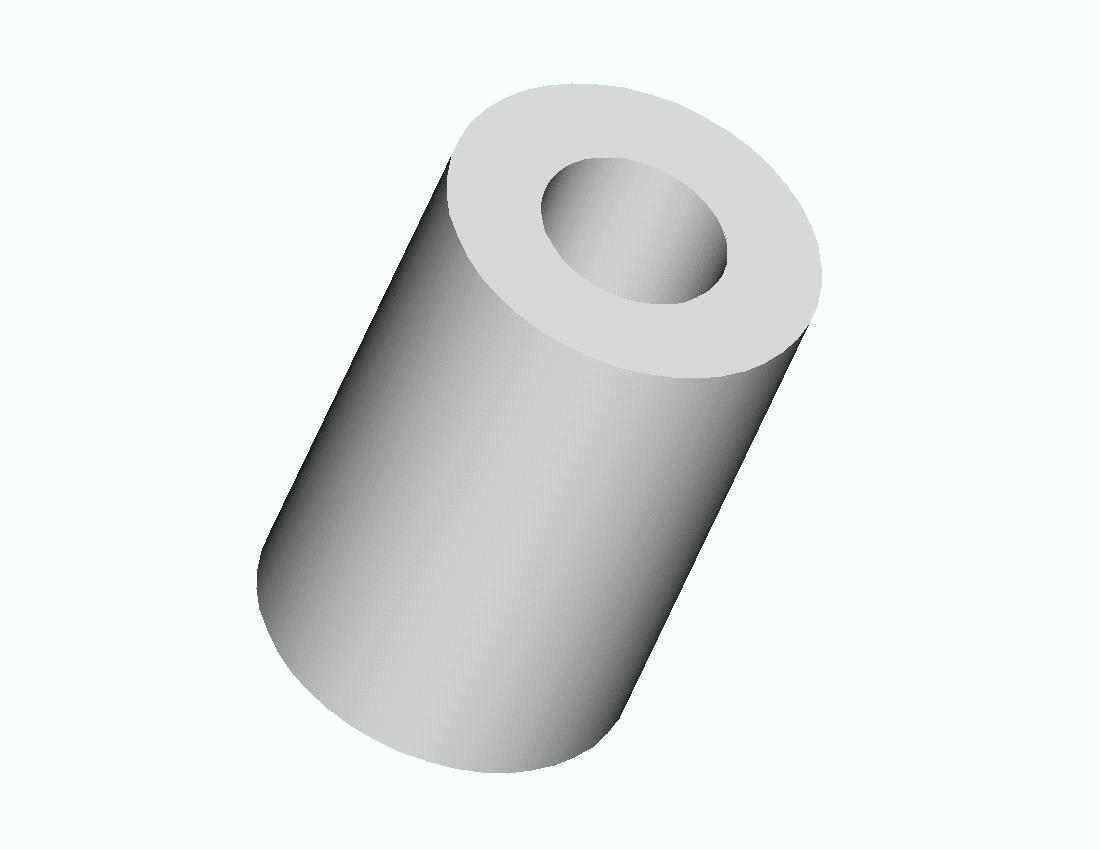
To illustrate this type of analysis consider the problem of finding the stresses in a thick open-ended cylinder with an internal pressure (such as a pipe discharging to the atmosphere). The steel cylinder below has an inner radius of 5 inches and an outer radius of 11 inches.
A cross section is shown below
In both drawings the length of the object is arbitrary and represents a segment of a long, open-ended cylinder. The Y axis is the axis of symmetry. The cylinder can be generated by revolving a rectangle 6 inches wide and of arbitrary height 360 degrees about the Y axis.
Since the height of the segment considered is arbitrary, we will use a segment 1 inch in height for the finite element model. The geometry is shown below.
The ANSYS solution to this problem is given next for an internal pressure of 1000 psi.
1. Start ANSYS
Use a quadrilateral element with axisymmetric behavior.
2. Preprocessor -> Element Type -> Add/Edit/Delete -> Add ->
select Quad 4 Node 42 -> OK -> Options (Element Behavior)-> Axisymmetric -> OK -> CloseEnter material property data for steel.
3. Preprocessor -> Material Props -> Material Models . . . -> Structural -> Linear -> Elastic -> Isotropic ->Enter Ex = 3.e7 and PRXY = 0.3 -> OK -> Close.
Create geometry for rectangle 1 inch by 6 inches starting 5 inches from Y axis. Note: In ANSYS the Y axis is always the axis of symmetry for axisymmetric problems..
4. Preprocessor -> Create -> Areas -> Rectangle ->By 2 Corners
Mesh the area and apply loads and boundary conditions.
5. Preprocessor -> Mesh -> Areas -> Free (Pick rectangular area)
6. Preprocessor -> Loads ->Apply ->Displacement -> On Lines (Pick the bottom line of the rectangle) uy = 0 along this line. This simply prevents rigid body motion in the Y direction. No other displacement boundary conditions are required. The radial movement is prevented by the 'hoop' tension in the cylinder.
Preprocessor -> Loads ->Apply ->Pressure -> On Lines (Pick the left hand line of the rectangle). Enter a pressure of 1000
7. Solution -> Solve -> Current LS ->OK
Check the deformed shape to see if it's reasonable. (The dotted line is the undeformed shape.)
8. General Post Processor -> Plot Results -> Deformed Shape . . . ->Def +undeformed -> OK
Examine the stresses ----------
9. General Postprocessor -> Plot Results -> Element Solu . . . (Pick Sx then Sy then Sz and examine each).
SX --------------------------------------
The SX stress is the radial stress that is equal to the pressure (-1000 psi) on the interior of the cylinder and is zero on the exterior. The stress legend varies from -1001 to -110. We will need to examine the computed values more closely evaluate this further.
SY --------------------------------------
The SY stress is the axial stress in the cylinder and should be zero since the ends are open. This is nearly so in the plot above.
SZ --------------------------------------
SZ is the 'hoop' stress perpendicular to the plane of this rectangle and varies from 1523 to 520 in the legend above.
We can calculate SX and SZ from solid mechanics formulas for thick walled cylinders. These equations give
At the inside of the cylinder SX = -1000 psi and SZ = 15210 psi
At the outside of the cylinder SX = 0 psi and SZ = 520 psi.
Thus the ANSYS calculated results agree pretty well with the theory.
Examine the stresses more closely at the boundaries.
Number the nodes and elements.
10. PlotCntls -> Numbering . . .-> Turn on Node & Element Numbers Zoom in on the inside and outside walls of the cylinder.
INSIDE ------------------------------------
List the stress results for Elements 1, 16, and 31.
11. List -> Results ->Element Solution . . . -> Stress -> Components -> OK.
PRINT S ELEMENT SOLUTION PER ELEMENT
***** POST1 ELEMENT NODAL STRESS LISTING *****
LOAD STEP= 2 SUBSTEP= 1
TIME= 2.0000 LOAD CASE= 0
THE FOLLOWING X,Y,Z VALUES ARE IN GLOBAL COORDINATES
ELEMENT= 1 PLANE42
NODE SX SY SZ SXY SYZ SXZ
1 -995.80 7.6070 1518.9 -46.247 0.0000 0.0000
3 -816.22 2.8291 1337.8 -46.213 0.0000 0.0000
37 -816.36 2.8243 1337.8 45.349 0.0000 0.0000
36 -995.93 7.6119 1518.9 45.315 0.0000 0.0000
ELEMENT= 16 PLANE42
NODE SX SY SZ SXY SYZ SXZ
36 -995.47 11.132 1520.2 -47.531 0.0000 0.0000
37 -815.90 1.2212 1337.4 -47.403 0.0000 0.0000
38 -815.62 1.2215 1337.6 44.196 0.0000 0.0000
35 -995.19 11.132 1520.5 44.067 0.0000 0.0000
ELEMENT= 31 PLANE42
NODE SX SY SZ SXY SYZ SXZ
35 -994.73 18.160 1522.9 -48.075 0.0000 0.0000
38 -814.76 -3.0243 1336.5 -47.906 0.0000 0.0000
34 -821.59 -3.2188 1334.7 43.696 0.0000 0.0000
20 -1001.2 18.360 1521.9 43.527 0.0000 0.0000
The computed SX and SZ stresses are within 0.4% of the theoretical values.
OUTSIDE ------------------------------------
List the stress results for Element 15.
12. List -> Results ->Element Solution . . . -> Stress -> Components -> OK.
ELEMENT= 15 PLANE42
NODE SX SY SZ SXY SYZ SXZ
16 -19.922 -0.64520 540.57 -8.2588 0.0000 0.0000
2 0.90585E-01 -1.4459 520.29 -8.2562 0.0000 0.0000
18 0.11328 -1.4457 520.31 8.1154 0.0000 0.0000
63 -19.900 -0.64542 540.58 8.1127 0.0000 0.0000
Notice at nodes 2 and 18 the SX stress is virtually zero and the SZ stress matches the theoretical value.
Next compare the computed and theoretical solutions for the radial displacement at the inside and outside of the cylinder.
Theoretical Values:
Displacement at Inside Surface = 0.305E-4 inches
Displacement at Outside Surface = 0191E-3 inches
List the ANSYS results
13. General Postprocessor -> List -> Results -> Nodal Solution . . . DOF ->All DOFs -> OK (A partial listing is shown below)
NODE UX UY
1 0.30353E-03 0.0000
2 0.19107E-03 0.0000
3 0.28572E-03 0.0000
4 0.27072E-03 0.0000
5 0.25798E-03 0.0000
6 0.24708E-03 0.0000
7 0.23770E-03 0.0000
8 0.22958E-03 0.0000
9 0.22255E-03 0.0000
10 0.21644E-03 0.0000
11 0.21113E-03 0.0000
12 0.20650E-03 0.0000
13 0.20248E-03 0.0000
14 0.19897E-03 0.0000
15 0.19594E-03 0.0000
16 0.19332E-03 0.0000
17 0.19110E-03-0.52763E-05
18 0.19107E-03-0.17508E-05
19 0.19107E-03-0.35069E-05
20 0.30376E-03-0.48288E-05
Nodes 1 and 20 are on the inside surface. Nodes 2 and 17 are on the outside surface. Note that the computed displacements are in agreement with the theoretical values.
© 2001 Kent L. Lawrence