Mapped Meshes
Meshes may be created by mapping a square with a regular array of cells onto a general quadrilateral or a cube containing a regular array of cells onto an arbitrary hexahedron. Examples below illustrate this process.
2D Meshes
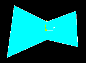
To mesh the region with two adjacent, but distinct areas shown below with quad elements
Element Type > Add/Edit/Delete > Add > Solid > Quad 4 node > OK >Close

Meshing > Mesh > Areas > Mapped > 3 or 4 sided (pick the two areas shown)
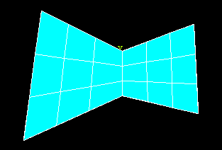
The areas above are four sided and were created from lines so that the two areas have a common boundary. If the areas do not have a common boundary, they can be glued together. A three-sided area example is shown below.
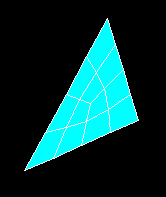
Triangular elements can used to create the meshes as well as quadrilaterals.
3D Meshes
Shown below is a segment of a cylinder.
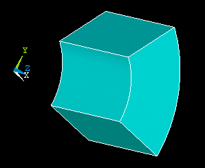
To create a brick mapped mesh, first select one of the brick elements from the element library.
Element Type > Add/Edit/Delete > Add > Solid > Brick 8 node > OK >Close
Meshing > Mesh > Volumes > Mapped > 4 to 6 sided (pick the volume shown)
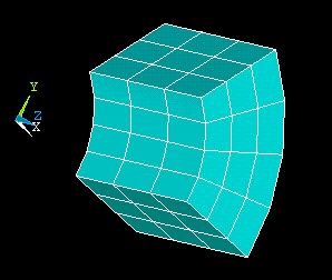
If a specific number of divisions is required along an edge of one of the 2D or 3D regions described above, go first
Meshing > Size Cntrls > Manual Size > Picked Lines (or All Lines) (set the element edge length or number of divisions and then pick the lines to be divided.)
An additional 3D example is shown below. The cylinder segment and the brick were created separately and then glued together.
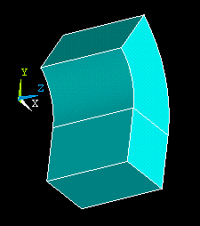
Meshing > Mesh > Volumes > Mapped > 4 to 6 sided (pick the two volumes shown)
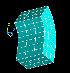
Gluing two areas or volumes creates a common boundary. Adding two areas or volumes creates a single area or volume and the single entity must be meshed.
© 1999 Kent L. Lawrence. All rights reserved.