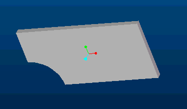
IGES Import
The IGES neutral file format provides a way to transfer files between different CAD systems and to other applications that utilize CAD geometry. The examples below demonstrate using IGES to import solid part models into ANSYS for FEM analysis.
PLANE STRESS ANALYSIS
A solid model is created in Pro/E and exported as an IGES file using the Pro/E default settings (export surfaces). By sure the planar surface is created in the X-Y plane. Save a copy > IGES

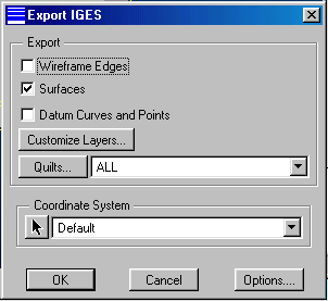
Quit Pro/E and start ANSYS
File > Import > IGES (use the ANSYS default setting. If you have difficulty, try again with the alternate option.)
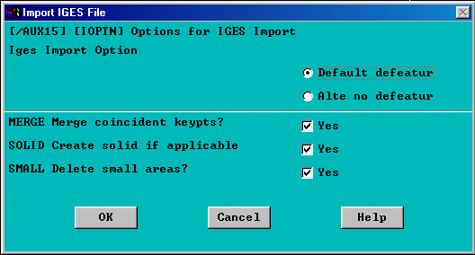
This brings the model into ANSYS as a solid.
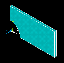
To perform plane stress analysis on this part, we need to mesh the X-Y plane area of the part.
Preprocessor > Element Type > Add/Edit/Delete > Add > Solid > Triangle 6 node > OK >Close
Meshing > Mesh > Areas > Free (Turn the solid around so you can see the X-Y plane and select that area for meshing.)
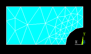
The imported solid model is no longer needed and may be deleted.
Plot > Volumes
Delete > Volumes and below (Select the volume)
Plot > Elements
Provide material properties and loads to solve the FEM problem of interest.
THREE DIMENSIONAL ANALYSIS
A solid model created in Pro/E is imported into ANSYS as in the above.
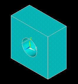
Since it is the solid we want to analyze, we mesh the solid.
Preprocessor > Element Type > Add/Edit/Delete > Add > Solid > Tet 10 node > OK >Close
Meshing > Mesh > Volumes > Free (Select the solid)
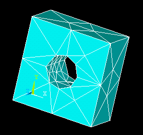
Now provide the material properties, loads, and boundary conditions to solve the FEM problem of interest.
© 2003 Kent L. Lawrence. All rights reserved.