|
Additions & Corrections for ANSYS Tutorial Releases 5.7 & 6.0 Kent L. Lawrence SDC Publications June 2002 |
|
|
Additions & Corrections for ANSYS Tutorial Releases 5.7 & 6.0 Kent L. Lawrence SDC Publications June 2002 |
|
The step sequence numbers are incorrect in a number of the Lesson tutorials. Just ignore the sequence numbering and move to the next step.
These step numbering changes and the additions shown below are incorporated in the 2nd printing and subsequent versions.
The figures shown below are just for your reference.
2-7 TUTORIAL 2B – SEATBELT COMPONENT
Add to these comments to Tutorial 2B following Figure 2-26
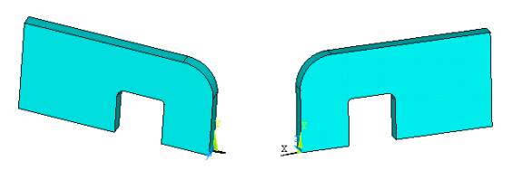
Figure 2-26 Seatbelt solid, front and back.
Important note: The mesh that follows was developed from an IGES geometry file. If you use the text file geometry definition, you may obtain a much different mesh. Use the modify mesh refinement tools to obtain a mesh density which produces results with accuracies comparable to those given below.
2-8 MAPPED MESHING
Add immediately following Figure 2-34
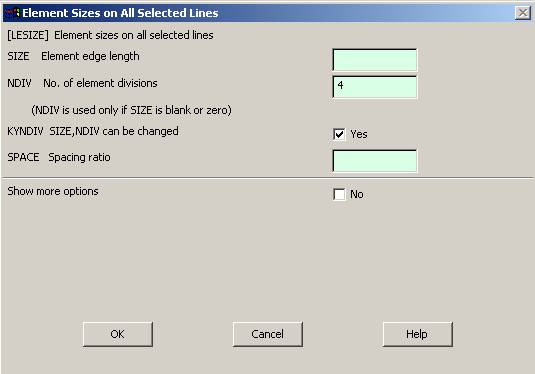
Figure 2-34 Element size on lines.
5. Main Menu > Preprocessor > Element Type > Add/Edit/Delete > Add > Solid > Quad 8node 183 > OK . (Use the 8-node quadrilateral element for the mesh.)
6. Main Menu > Preprocessor > Meshing > Mesh > Mapped > 3 or 4 sided > Pick All
3-4 TUTORIAL 3A – PRESSURE VESSEL
Change 'a' to 'AL' in the last line of the text file for Tutorial 3A
AL, 1, 2, 3, 4, 5, 6, 7 ! Area defined by lines 1 thru 7
4-4 TUTORIAL 4A - PRESSURE VESSEL
'Loads' missing in Step 11. It should read
Utility Menu > List > Loads > DOF Constraints > On Areas
4-7 TUTORIAL 4B – USING SYMMETRY
Switch the order of Y & Z axes in the instructions before and after Figure 4-13. It should read as shown below.
3. Import a 15-degree solid model of the pressure vessel (or use ANSYS commands to create the solid) Select the ten-node tet, element number 187.
Displacement Boundary conditions are applied to restrain displacement in the Z
direction on the X-Y (left) face of the wedge.
4. Main Menu > Preprocessor
> Loads > Define Loads > Apply > Displacement > On Areas
Select the X-Y face (left side in figure below) and set UZ = 0.
On the symmetric face of the wedge apply Symmetric Displacement conditions.
5. Main Menu > Preprocessor > Loads > Define Loads > Apply > Displacement > Symmetry B.C. > On Areas (Select the symmetric face, right side in figure) > OK.
The S’s in the figure below indicate the symmetric boundary conditions.
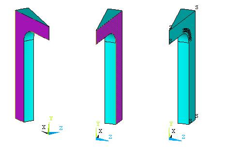
Figure 4-13 Applying symmetric boundary conditions.
Apply a pressure of 35 N per mm2 to the interior surface and restrain the lower surface of the wedge from displacement in the Y direction.
4-11 TUTORIAL 4D – SWEPT MESH
Fifth step should read
5. Do the same for the height with NDIV = 6.
7-6 TUTORIAL 7B – UNIFORM TEMPERATURE CHANGE
After Figure 7-9, step 5 should read as shown.
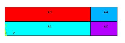
Figure 7-9 Areas.
5. Use manual size controls to divide the interior horizontal and vertical lines segments into 12, 4, 4, and 4 divisions. Then Mapped Mesh > 3 or 4 sided > Pick All.
7-7 TUTORIAL 7C – THERMAL STRESS
In the paragraph just before Figure 7-13, change 10,0 to 0,10
After Figure 7-17, insert step 16 to insure that the structural element option is set to axisymmetric.
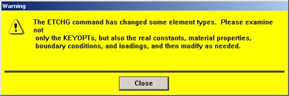
Figure 7-17 Warning of element change.
Set the PLANE82 structural element options to axisymmetric.
16. Main Menu > Preprocessor > Element Type > Add/Edit/Delete > PLANE82 > Options > K3 Axisymmetric > OK
8-3 TUTORIAL 8A – PLATE WITH HOLE, P-METHOD SOLUTION
In step 5 change First Set to Last Set as shown below.
5. Main Menu > General Post Processor > Read results, Last Set > Plot Results > Contour Plot > Element Solution >Stress SX
The problem is solved for each
p-level considered, so we want to plot the last solution.
Please send your comments to lawrence@mae.uta.edu